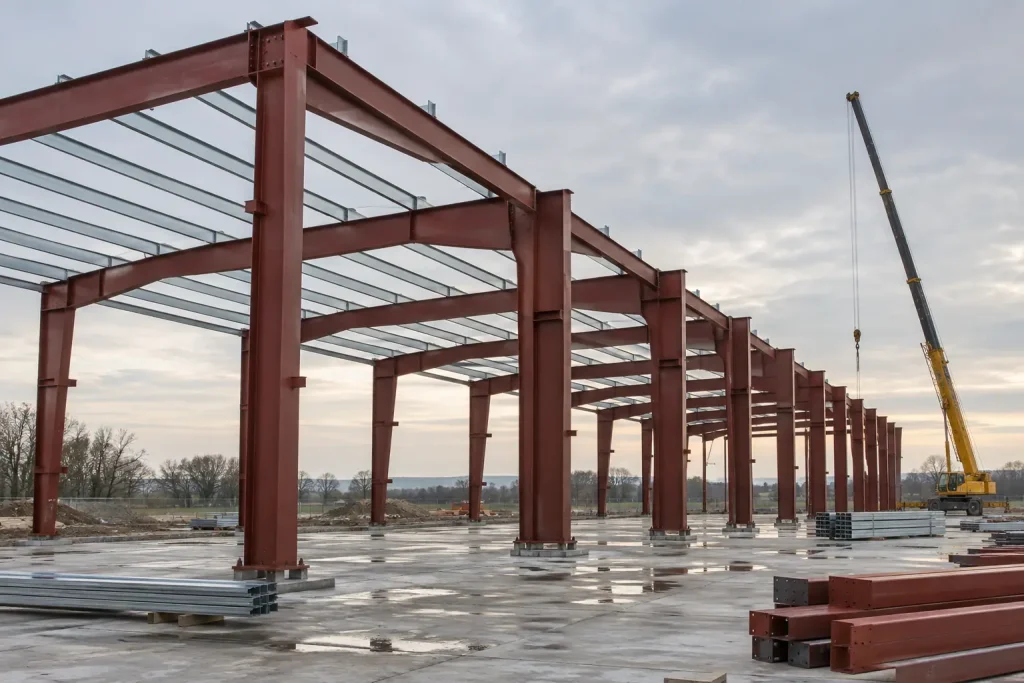
A pre-engineered metal building (PEMB) is a steel building whose frames, purlins, girts, bracing and panels are designed and fabricated by one manufacturer for a specific order, then bolted together on site.
Key takeaways
- The 2024 International Building Code adds a special inspection category for metal building systems, Section 1705.2.6, according to MBMA Common Industry Practices (2024 edition) and the ICC Statement of Special Inspections template.
- The MBMA Performance Guide Specification (August 2026) lists AISC 360-22 for hot-rolled and built-up frames and AISI S100-16 (2020) for cold-formed purlins and girts, with 55 ksi minimum yield for purlins, girts and eave struts.
- OSHA 29 CFR 1926.758 requires at least 4 anchor rods per column and 50 percent of rigid-frame bolts, or the manufacturer’s number if greater, tightened before the crane lets go.
- MBMA sets drift options from H/60 to H/400 for 10-year wind; the federal Unified Facilities Guide Specification UFGS 13 34 19 (August 2026) sets H/480, which is 0.5 in. of sway at a 20 ft eave against 4.0 in. at H/60.
- Under MBMA Common Industry Practices Section 3.2.2, the manufacturer does not design the foundation; its anchor rod plan shows only rod location, diameter and projection.
What is a pre-engineered metal building?
A pre-engineered metal building is a complete structural and envelope system designed by the manufacturer as one unit. The MBMA guide specification (August 2026, Section 1.4 A) requires that “all components of the system shall be supplied or specified by the same manufacturer”, and its scope excludes foundations, the floor slab, cranes, plumbing, electrical, HVAC and interior finishing.
“Pre-engineered” does not mean one stock design sold off a shelf. Each order is designed to the loads, code edition and dimensions in the order documents, and the manufacturer’s engineer, registered in the project’s jurisdiction, seals a Letter of Certification and design calculations (MBMA Common Industry Practices, Section 3.3.2). The same section says that seal does not make the manufacturer’s engineer the engineer of record for the whole project.
OSHA calls the same product a “systems-engineered metal building” and gives it its own erection rule, 29 CFR 1926.758. MBMA reports that a metal building shell can be completed in 30 to 50 percent less time than competing framing systems (MBMA, accessed October 2026); that is an industry claim about the shell, not the full project. Owners choosing who to hire, rather than how the system works, will find bid scope and contractor checks on our page about metal building contractors.
What are the parts of a pre-engineered metal building?
A PEMB has four structural layers: primary frames, secondary framing, bracing and cladding, all tied to the foundation by anchor rods. MBMA lists primary framing as clear span or modular rigid frames, truss systems, braced end frames, endwall columns and canopy beams, and secondary framing as purlins, girts, eave struts and flange bracing (MBMA guide specification, August 2026, Section 1.1).
| Component | Typical member | Material and minimum yield | Design standard | Source |
|---|---|---|---|---|
| Rigid frame (columns and rafters) | Built-up tapered I section welded from plate | ASTM A1011, A1018, A529 or A572, 50 or 55 ksi | AISC 360-22 | MBMA guide spec 2.1 B |
| Hot-rolled frame members | Wide-flange or other rolled shapes | ASTM A36 at 36 ksi; A572 or A992 at 50 ksi | AISC 360-22 | MBMA guide spec 2.1 A |
| Purlins (roof) | Cold-formed Z section, lapped over frames | ASTM A1011 or A1039 Grade 55 primed, A653 Grade 55 galvanized, 55 ksi | AISI S100-16 (2020) | MBMA guide spec 2.2 A |
| Girts (walls) | Cold-formed Z or C section | Grade 55, 55 ksi | AISI S100-16 (2020) | MBMA guide spec 2.2 A |
| Eave strut | Cold-formed C section at the roof edge | Grade 55, 55 ksi | AISI S100-16 (2020) | MBMA guide spec 2.2 A |
| Rod or cable X-bracing | Rods or cables in braced wall and roof bays | ASTM A529 rod at 50 ksi; ASTM A475 cable | AISC 360-22 | MBMA guide spec 2.1 F |
| Roof and wall panels | Standing seam or through-fastened steel sheet | ASTM A653 G90 or A792 AZ55 coated sheet, 50 ksi | ASTM E1592 test; UL 580 uplift class | MBMA guide spec 2.3, 2.4 |
| Anchor rods | Rods cast into the foundation | Specified by the foundation designer | OSHA 1926.758(b): at least 4 per column | OSHA; MBMA CIP 3.2.2 |
Purlins sit between two labels. The MBMA Roof Framing Design Guide, 2nd edition (June 2024) calls purlins “the primary load carrying components of the roof system” but notes they are “commonly called secondary members with respect to the entire building system”. Z purlins are usually lapped over the frames with at least two structural bolts through the webs, which makes them continuous and lighter for the same span.
Coating choice is a code-adjacent detail owners often miss. The MBMA guide specification (Section 2.3) says G60 galvanized sheet “should be used only for interior applications”, while G90 galvanized or AZ55 aluminum-zinc coatings suit exposed exterior use.
Frame type is the next choice after the parts. The federal guide specification UFGS 13 34 19 (August 2026, Section 1.4.1) names six primary frame types, and its bay spacing options are 20, 25 or 30 ft with eave heights of 16, 20, 24 or 28 ft.
| Frame type (UFGS 13 34 19 term) | What it is (UFGS 1.4.1) | Typical use (CB&C editorial) |
|---|---|---|
| Rigid clear span | Solid-member frame with no interior columns | Warehouses, gyms, hangars that need open floor |
| Rigid modular | Solid-member frame with interior columns | Very wide buildings where interior columns are acceptable |
| Truss-frame clear span | Truss-member frame, no interior columns | Long spans where a deep truss is lighter than a plate rafter |
| Truss-frame modular | Truss-member frame with interior columns | Wide footprints with truss roofs |
| Long bay | Solid or truss frame without interior columns, named for long bays between frames | Projects that want fewer frame lines |
| Lean-to | Frame partly supported by another structure | Additions and sheds against an existing building |
Which codes and standards govern PEMB design?
A PEMB is designed under the building code your jurisdiction adopted, its load standard and two steel specifications. As of October 2026, MBMA says its Metal Building Systems Manual, 2024 edition, conforms to the 2024 IBC and ASCE 7-22 (MBMA Design Resources), and its guide specification bases its reference list on the 2024 IBC.
| Document | Edition named | What it controls on a PEMB | Source |
|---|---|---|---|
| International Building Code (IBC) | 2024 | Code path, construction documents, special inspection (Section 1705.2.6), deflection limits (Table 1604.3) | MBMA guide spec 1.3; MBMA CIP 3.2 |
| ASCE/SEI 7-22 | 7-22 with Supplements 1 to 3 | Wind, snow, rain (Chapter 8), seismic and tornado (Chapter 32) loads | ASCE; MBMA guide spec 1.4 |
| AISC 360 | 360-22 | Hot-rolled and built-up primary frames, by LRFD or ASD | AISC; MBMA guide spec 1.3 A |
| AISI S100 | S100-16 (2020) with S2-20 | Cold-formed purlins, girts and eave struts | MBMA guide spec 1.3 C |
| AISC Design Guide 3 | 2nd edition, 2003 | Serviceability: deflection and drift choices | MBMA guide spec 1.3 B |
| AWS D1.1 and D1.3 | D1.1:2020; D1.3:2018 | Welding of plate frames and of sheet steel | MBMA guide spec 1.3 |
| MBMA Metal Building Systems Manual | 2024 | Load combinations practice, crane guidance, nomenclature, climatological data | MBMA Design Resources |
| IAS AC472 | 2023 criteria | Accreditation of the manufacturer’s design and fabrication inspection program | IAS; MBMA guide spec 1.7 A |
Edition matters because states and cities adopt codes on their own schedule. MBMA Common Industry Practices Section 3.2.1 makes the owner, or the owner’s design professional, responsible for naming “the applicable code or standard, including the specific edition”. Wind provisions for Broward and Miami-Dade are stricter again; our guide to high-velocity hurricane zone construction covers them. Insulation and air leakage follow the energy code your state adopted, which our commercial energy code by state report tracks.
Who is responsible for what on a PEMB order?
Four parties split a PEMB: the owner (MBMA’s “End Customer”) sets design criteria, the builder orders the system, the manufacturer designs and fabricates it, and the erector assembles it. MBMA Common Industry Practices (2024 edition, Section 1.2) defines each role and says the builder “is an independent contractor and is not an agent for the Manufacturer”.
- Set design criteria. The owner or engineer of record supplies the code and edition, building geometry, all loads (live, snow, wind, tornado, seismic, collateral, auxiliary), risk category and exposure factors, and serviceability limits (MBMA CIP 3.2.1, items 1 to 9).
- Builder orders. The builder passes every criterion to the manufacturer in the order documents. Under Section 3.2.1, item 3, “the Manufacturer assumes that no such loads or conditions exist” unless they are written in.
- Manufacturer designs. The manufacturer’s engineer seals the Letter of Certification and calculations listing codes, standards and loads (CIP 3.3.2).
- Anchor rod plan. The manufacturer issues rod location, diameter and projection only; a local engineer designs footings, embedment and slab (CIP 3.2.2).
- Fabrication. Frames and cold-formed parts are made at a plant; every MBMA manufacturer member is AC472 accredited and IAS audits member plants annually (MBMA Accreditation).
- Erection. The erector checks concrete dimensions and anchor rod locations before setting steel (CIP 6.4), then erects to OSHA 1926.758 and tightens bolts per the RCSC specification (MBMA guide spec 3.2 E).
- Special inspection. The approved agency inspects the erected system under IBC 2024 Section 1705.2.6 before final approval.
Errors in the slab, foundation or anchor rods are costly for the owner. CIP Section 6.4 says the owner pays “all additional costs resulting from errors in the concrete slab and foundation or in the setting of anchor rods”, except where the builder built that work. When one firm carries design and construction under a single contract, our page on design-build contractors explains how that changes the chain.
What loads and stiffness limits should the owner specify?
The order must carry every load beyond the frame’s own weight, plus the stiffness the walls and roof need. The MBMA guide specification (August 2026, Section 1.4) sets a 20 psf minimum roof live load, reducible per code, and leaves blanks for collateral load (sprinklers, mechanical and electrical systems, ceilings), solar-ready load, snow, wind, rain, tornado and crane loads.
The arithmetic below uses the published roof example in the MBMA Roof Framing Design Guide (2024, Section 5.5.4.7): four 25 ft bays, 12 purlin lines at 5 ft on center, 8ZS2.75×085 purlins in the end bays and 8ZS2.75×059 in the interior bays, a 1/2:12 slope, 3 psf dead load and 20 psf live load. The 5 psf collateral row is a CB&C illustration of an owner-supplied value, not a code minimum.
| Step | Inputs | Arithmetic | Result | Source |
|---|---|---|---|---|
| Purlin line load, MBMA example | 3 psf dead + 20 psf live, 5 ft spacing | (3 + 20) x 5 | 115 plf | MBMA Roof Framing Design Guide 5.5.4.7 |
| Add 5 psf collateral (illustration) | 3 + 5 + 20 psf, 5 ft spacing | (3 + 5 + 20) x 5 | 140 plf, 21.7% more | CB&C arithmetic |
| Load on one interior rafter, no collateral | 23 psf, 25 ft bay | 23 x 25 | 575 plf | CB&C arithmetic |
| Load on one interior rafter, with collateral | 28 psf, 25 ft bay | 28 x 25 | 700 plf | CB&C arithmetic |
| Purlin deflection allowed at L/150 (dead plus snow, or 10-year wind) | 25 ft span = 300 in. | 300 / 150 | 2.0 in. | MBMA guide spec 1.4 O |
The point of the arithmetic: 5 psf left off the order is a 21.7% heavier purlin load that nobody designed for. MBMA guide specification Section 1.4 E also bars applying collateral loads to roof panels, so hanging items must land on purlins or frames.
Stiffness is the second half. A drift limit caps how far the eave may sway in wind as a fraction of eave height H, so H/100 on a 20 ft (240 in.) eave allows 2.4 in.; a deflection limit does the same for sag along a member’s span L. The MBMA guide specification lists drift options of H/60, H/100, H/200 and H/400 for 10-year wind and notes that “H/60 or H/100 is common for metal wall panels”, while masonry, concrete or glass “may require lower allowable drift limits”. UFGS 13 34 19 (August 2026, Section 1.6.3) sets H/480 for federal work.
| Limit | Applies to | Sway or sag at a 20 ft eave or 25 ft span | Source |
|---|---|---|---|
| H/60 | Drift, 10-year wind, metal walls | 4.0 in. | MBMA guide spec 1.4 P |
| H/100 | Drift, 10-year wind, metal walls | 2.4 in. | MBMA guide spec 1.4 P |
| H/200 | Drift, 10-year wind | 1.2 in. | MBMA guide spec 1.4 P |
| H/400 | Drift, 10-year wind | 0.6 in. | MBMA guide spec 1.4 P |
| H/480 | Drift, 10-year MRI wind, federal projects | 0.5 in. | UFGS 13 34 19, 1.6.3 |
| L/180 | Primary frame, roof snow | 1.67 in. per 25 ft of span | MBMA guide spec 1.4 O |
| L/90 | Wall girts, 10-year wind | 3.33 in. | MBMA guide spec 1.4 O |
| L/60 | Metal panels, 10-year wind | 5.0 in. | MBMA guide spec 1.4 O |
How is a pre-engineered metal building erected and inspected?
Erection of a pre-engineered metal building falls under OSHA 29 CFR 1926.758, which applies the steel erection subpart except the general column anchorage rule (1926.755) and the open web joist rule (1926.757). Inspection falls under IBC 2024 Section 1705.2.6, which MBMA Common Industry Practices describes as new special inspection requirements for metal building systems.
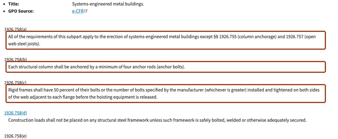
- 1926.758(b): each structural column is anchored by at least 4 anchor rods.
- 1926.758(c): rigid frames have 50 percent of their bolts, or the manufacturer’s number if greater, installed and tightened on both sides of the web at each flange before hoisting equipment is released.
- 1926.758(e): where girts or eave struts share connection holes, at least one bolt with its wrench-tight nut stays on the first member, unless a manufacturer-supplied seat secures it.
- 1926.758(g) and (h): purlins and girts are not fall-arrest anchorages without written approval from a qualified person, and purlins are walked on only to install safety systems after permanent bridging and fall protection are in place.
The MBMA guide specification adds two erection rules owners can write into the contract: bracing furnished by the manufacturer “cannot be assumed to be adequate during erection” (Section 3.2 F1), and no field cutting or modifying of structural members without the manufacturer’s approval (Section 3.2 G). Fabrication tolerances are published too: MBMA CIP Table 9.1 allows plus or minus 1/8 in. on cold-formed member length and a minimum thickness of 0.95 times design thickness.
Plan the special inspection at permit stage. The ICC Statement of Special Inspections template now carries a “Metal Building Systems (1705.2.6)” line, and IBC Section 1704.2.5.1 lets a building official accept an approved fabricator in place of in-plant inspection; IAS says AC472 ties to IBC Chapter 17. Our guide to commercial building permits explains when the statement is filed.
How does a PEMB compare with conventional structural steel?
The difference is who designs the system and which members carry the roof. A PEMB is designed by its manufacturer as one package of tapered plate frames and cold-formed purlins and girts (MBMA Common Industry Practices, Section 3.3.2); a conventional steel building is designed by the project’s engineer of record from rolled shapes, joists and deck sourced from several suppliers.
| Item | Pre-engineered metal building | Conventional structural steel | Source |
|---|---|---|---|
| Structural designer | Manufacturer’s engineer, sealing for the system only | Project engineer of record | MBMA CIP 3.3.2 |
| Primary members | Built-up tapered I frames, 50 or 55 ksi plate | Rolled wide-flange beams and columns | MBMA guide spec 2.1 |
| Roof framing | Lapped cold-formed Z purlins, AISI S100 | Steel joists (SJI 100) and roof deck | MBMA guide spec 2.2; MBMA Roof Framing Design Guide |
| Supply | Single source for frame, secondary and panels | Separate fabricator, joist and deck suppliers | MBMA guide spec 1.4 A |
| OSHA erection rule | 29 CFR 1926.758 | 29 CFR 1926.755 column anchorage and the rest of Subpart R | OSHA |
| Plant credential to ask for | IAS AC472 | Approved fabricator per IBC 1704.2.5.1, or in-plant special inspection | IAS; ICC |
| Shell schedule claim | 30 to 50% less time than competing framing (MBMA claim) | Set by design, detailing and fabrication queue | MBMA |
Neither system is limited to a plain metal look: UFGS 13 34 19 (Section 2.3.2) lists load-bearing wall and multistory configurations, and many PEMB shells carry masonry or concrete walls, which is where the drift limit in the previous section matters. For concrete shells on large distribution buildings, our guide to tilt-up construction compares the code paths, and the shell trade-offs for storage and logistics are on our warehouse construction page.
What does a PEMB cost, and what moves the price?
In federal purchase records that state the size, a pre-engineered metal building package cost $16.17 to $17.30 per sq ft for 1,200 to 8,000 sq ft buildings (2021 to 2024), and an erected 1,440 sq ft PEMB shell cost $50.20 per sq ft in 2023. The BLS index for complete metal building systems (WPU107901) rose 4.7% in the 12 months to September 2026.
| Record | Scope | Per sq ft | Date | Source |
|---|---|---|---|---|
| 80 x 100 x 20 ft metal building, 8,000 sq ft, Federal Law Enforcement Training Center | Package | $16.17 | Jun 2021 | USAspending |
| 48 x 30 x 13 ft PEMB, 1,440 sq ft, USDA Agricultural Research Service, California | Erected shell | $50.20 | Sep 2023 | USAspending |
| 10,023 sq ft insulated pre-engineered building, U.S. Fish and Wildlife Service, Texas | Slab, delivery, erection, insulation | $122.10 | Sep 2025 | USAspending |
These are federal awards, which can carry prevailing wages and vendor margins; all ten records we found, with sizes and finished-building ranges, are in our guide to steel building prices. Steel moved faster than the package: Bureau of Labor Statistics data show steel mill products (WPU1017) at 388.580 in September 2026 (preliminary), up 27.6% from 304.579 a year earlier (BLS PPI, re-checked October 26, 2026).
| BLS series | ID | Sept 2025 | Sept 2026 (P) | 12-month change |
|---|---|---|---|---|
| Prefabricated metal building systems (complete packages) | WPU107901 | 594.686 | 622.532 | +4.7% |
| Steel mill products | WPU1017 | 304.579 | 388.580 | +27.6% |
| Hot rolled bars, plates and structural shapes | WPU101704 | 277.952 | 319.693 | +15.0% |
| Fabricated structural metal | WPU107405 | 359.691 | 380.544 | +5.8% |
Design inputs move weight, and weight moves price. In the MBMA roof example, adding 5 psf of collateral load raises the purlin line load from 115 to 140 plf, and a drift limit tightened from H/100 to H/400 cuts allowed sway from 2.4 in. to 0.6 in. at a 20 ft eave, which needs stiffer frames. An expandable endwall in UFGS 13 34 19 (Section 1.4.3) carries full-bay loads against one-half of a bay load for a fixed endwall frame. Monthly series are tracked in our commercial construction price index.
What do common guides get wrong about PEMBs?
Several top-ranking guides blur three points: what “pre-engineered” means, who carries engineering responsibility, and how fast a PEMB is. The table sets five claims, described neutrally, against the primary document that answers it, so an owner can quote the source in a bid review.
| What several guides say | What the primary source says | Source |
|---|---|---|
| A reference encyclopedia entry describes a pre-engineered building as one supplier design built many times. | Each order is designed to the loads and code edition in its order documents, and the design is sealed by an engineer registered where the building stands. | MBMA CIP 3.2.1, 3.3.2 |
| Manufacturer guides say a PEMB is built in “half the time” of conventional construction. | MBMA’s own figure is 30 to 50 percent less time for the shell, compared with competing framing systems. | MBMA |
| Guides imply the manufacturer’s engineer is the project engineer. | Sealed calculations do not make the manufacturer’s engineer the engineer of record, and the manufacturer is not responsible for foundation design. | MBMA CIP 3.2.2, 3.3.2 |
| Guides list purlins and girts as minor secondary parts. | Purlins are “the primary load carrying components of the roof system”; secondary refers only to their place in the whole building. | MBMA Roof Framing Design Guide, Ch. 1 |
| Guides apply the general OSHA column anchorage rule, 1926.755, to metal buildings. | 1926.758(a) excludes 1926.755 for systems-engineered metal buildings; 1926.758(b) sets the 4-rod minimum. | OSHA 1926.755; OSHA 1926.758 |
Should your project use a pre-engineered metal building?
A pre-engineered metal building fits low-rise projects with repeating frame bays and a simple roof shape, where the owner can fix loads and openings before fabrication. Bridge cranes in severe or continuous severe service (Service Class E or F, which the MBMA guide specification sends to the AIST TR-13 mill building guide) and brittle wall finishes are the two conditions that change the design most.
| If | Then | Rule or source |
|---|---|---|
| The building is low-rise with repeating bays of 20 to 30 ft and a single or multiple gable roof | Price a PEMB; it is the standard case in UFGS 13 34 19 | UFGS 13 34 19, 1.4.6, 2.3.2 |
| The roof shape or framing is irregular | Price conventional structural steel, tilt-up or concrete as well | MBMA guide spec 1.4 A (single-source system) |
| Bridge cranes are in Service Class E or F | Require crane design to AIST TR-13 and price conventional steel too | MBMA guide spec 1.4 N |
| Walls are masonry, concrete or glass | Have the engineer of record set a lower drift limit, such as H/200 or H/400, in the order | MBMA guide spec 1.4 P; AISC Design Guide 3 |
| Walls are metal panels | H/60 to H/100 drift is the common range | MBMA guide spec 1.4 P |
| The project is federal | Plan for H/480 drift and an MBMA-member manufacturer with at least 5 years of experience | UFGS 13 34 19, 1.6.3 |
| Sprinklers, ducts, ceilings or solar may be added later | Write collateral and solar-ready loads in psf into the order now | MBMA guide spec 1.4 E, F; MBMA CIP 3.2.1 |
| The building may grow | Specify an expandable endwall frame for full-bay loads | UFGS 13 34 19, 1.4.3 |
For ground-up projects where the structural system is still open, our guide to new commercial construction sets PEMB beside steel, concrete, masonry and tilt-up. CB&C is a matching service, not a contractor or engineer, and this page is not engineering advice; the engineer of record for your project confirms loads and limits.
Buying a packaged building is covered in our metal building kits guide, and the choice of frame material in our red iron building guide.
How we compiled this
We read 13 primary documents in October 2026: the MBMA Performance Guide Specification (August 2026), MBMA Common Industry Practices (2024 edition), the MBMA Roof Framing Design Guide (2024), MBMA and IAS accreditation pages, OSHA 29 CFR 1926.758 and 1926.755, UFGS 13 34 19 (August 2026), the ICC special inspection template, ASCE and AISC standard pages, and the BLS producer price file. On October 26, 2026 we added federal award records from USAspending.gov for the price section. The ICC code text was not reachable without a CAPTCHA, so IBC section citations come from MBMA and ICC documents that quote them. Arithmetic rows labeled CB&C are our calculations from the inputs shown.
Frequently asked questions
What is the difference between a pre-engineered metal building and a regular steel building?
A pre-engineered metal building is designed by its manufacturer as one system of tapered plate frames, cold-formed purlins and girts, and panels, sealed by the manufacturer’s engineer under MBMA Common Industry Practices Section 3.3.2. A conventional steel building is designed by the project’s engineer of record from rolled shapes, joists and deck, and its erection falls under OSHA 1926.755 rather than 1926.758.
Do pre-engineered metal buildings meet building codes?
Yes, when the order names the adopted code and edition. MBMA says its 2024 Metal Building Systems Manual conforms to the 2024 IBC and ASCE 7-22, and its August 2026 guide specification references AISC 360-22 and AISI S100. The owner supplies the code, loads and factors; MBMA Common Industry Practices Section 3.2.1 says the manufacturer assumes no load that is not written into the order.
What is the framing system in a pre-engineered metal building?
Primary framing is rigid frames: built-up tapered I-section columns and rafters of 50 or 55 ksi plate, designed to AISC 360-22. Secondary framing is cold-formed Z or C purlins, girts and eave struts of Grade 55 steel, designed to AISI S100, with rod or cable X-bracing in braced bays, per the MBMA Performance Guide Specification (August 2026).
How long does it take to build a pre-engineered metal building?
MBMA states a metal building shell can be completed in 30 to 50 percent less time than competing framing systems. That figure covers the shell only. Foundations, the special inspection required by IBC 2024 Section 1705.2.6, fabrication queue and interior work add to the schedule, so ask each bidder for fabrication and delivery dates in writing.
Who designs the foundation for a pre-engineered metal building?
A local engineer hired by the owner or builder designs it, not the manufacturer. MBMA Common Industry Practices Section 3.2.2 says the manufacturer’s anchor rod plan shows only rod location, diameter and projection. OSHA 1926.758(b) requires at least 4 anchor rods per column, and Section 6.4 puts the cost of anchor rod errors on the owner unless the builder did that work.
What is a collateral load on a metal building?
Collateral load is the weight of permanent items hung from the structure other than the building itself: sprinklers, mechanical and electrical systems and ceilings, per the MBMA guide specification (August 2026, Section 1.4 E). It is written in psf on the order and is not applied to roof panels. In the MBMA roof example, 5 psf of collateral raises purlin load from 115 to 140 plf.
How much does a pre-engineered metal building cost?
In federal purchase records, the PEMB package alone cost $16.17 to $17.30 per sq ft for 1,200 to 8,000 sq ft buildings bought from 2021 to 2024. An erected 1,440 sq ft shell cost $50.20 per sq ft in 2023, and a 10,023 sq ft insulated building with its slab cost $122.10 per sq ft in 2025. Loads, size and finish move the number.
Sources
- Metal Building Systems Performance Guide Specification, Section 13 34 19, Metal Building Manufacturers Association, August 2026, accessed October 20, 2026.
- Common Industry Practices, 2024 Edition, Metal Building Manufacturers Association, published January 2025, accessed October 20, 2026.
- Roof Framing Design Guide for Metal Building Systems, 2nd Edition, MBMA with the AISI Education Committee, June 2024, accessed October 20, 2026.
- Design Resources (Metal Building Systems Manual, 2024 Edition), MBMA, accessed October 20, 2026.
- Metal building attributes, MBMA home page, accessed October 20, 2026.
- Accreditation (AC472 and AC478), MBMA, accessed October 20, 2026.
- Metal Building Systems Inspection Programs (AC472), International Accreditation Service, accessed October 20, 2026.
- 29 CFR 1926.758, Systems-engineered metal buildings, OSHA, accessed October 20, 2026.
- 29 CFR 1926.755, Column anchorage, OSHA, accessed October 20, 2026.
- UFGS 13 34 19, Metal Building Systems, USACE, NAVFAC and AFCEC, August 2026, accessed October 20, 2026.
- Statement of Special Inspections template, International Code Council, accessed October 20, 2026.
- ASCE/SEI 7-22, Minimum Design Loads and Associated Criteria for Buildings and Other Structures, American Society of Civil Engineers, accessed October 20, 2026.
- ANSI/AISC 360, Specification for Structural Steel Buildings, American Institute of Steel Construction, accessed October 20, 2026.
- Producer Price Index commodity data, current file (wp.data.0.Current), U.S. Bureau of Labor Statistics, downloaded October 20 and October 26, 2026.
- Federal contract award records (three awards linked in the price section), USAspending.gov, accessed October 26, 2026.